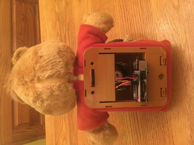
Following Tinkernut’s example, I have installed Mycroft into a revamped Teddy Ruxpin.
3 Likes
Soooo good!!!
Do you just feed audio in and the bear handles the mouth and eye movement, or are these controlled from the GPIO pins on the Pi, or something something else?
Thank you Kris. This is similar to Tinkernut’s Alexa-Ruxpin project. I gutted the animatronic. Replaced the old 5-wire Servo servos with new 9g 3-wire servos and connected the eyes, nose, and mouth directly to the servos with pushrods. The original setup used rubber wheels. I also replaced the 8 ohm, 1/2 watt speaker with an 8 ohm, 1 watt speaker. It is a 3-inch round speaker, so it was a direct replacement. I then built a prototype HAT for the RPi. I added a 3-watt i2s amplifier (mono output) and an Arduino Nano33 IoT. The Arduino runs the servos. The eyes blink on a timer routine, and the nose/mouth move according to a digital audio stream that I tap off the i2s output.
This HAT can be moved to the new RPi 4 or any 40-pin GPIO matching SBC, like an Odroid-N2. I’m still using an RPi 3B+ because the other system produce too much heat, and I’m running the animatronic fully closed. The only line out right now is a single USB power cord that runs to the RPi. Yes, the 3 small microservos and the amp all draw power from the RPi 5vout pin. It is a very minimal and very clean build. As soon as I have a 3 amp (or greater) power converter board (think PowerBoost 1000C on steroids), I will run from a rechargeable battery.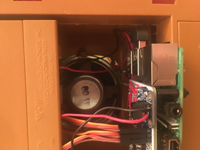
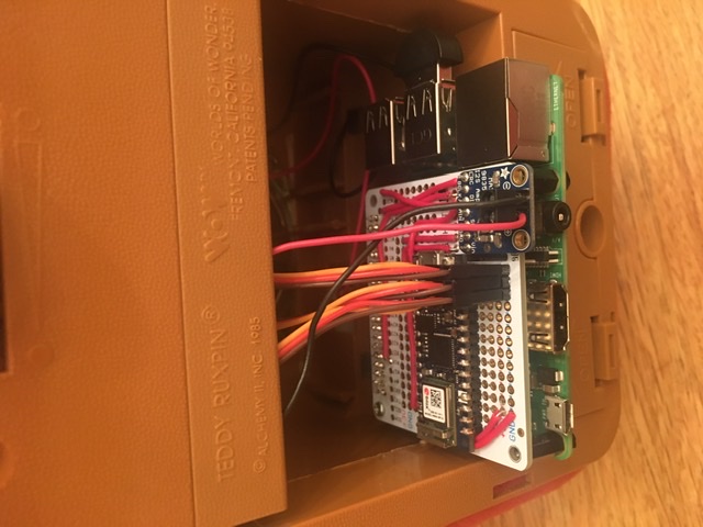
Currently, the Arduino (with servos) runs independent of instruction from the RPi/Mycroft. It only uses the digital audio line. However, it is possible to pass instructions from the RPi to the Arduino on the TX/RX pins (I don’t like using the clumsy USB cable). This would require 2 extra wires be added to the HAT. Then, with a few code tweaks on the Arduino, the RPi can override the default servo movement. This is planned for the next animatronic, which will have a camera and head movement with visual tracking, facial recognition, and object identification. Thus the need for a more powerful computer.
3 Likes
Very cool and looks very tidy indeed. It sounds well planned and well executed!
If you are interested in showing it off on our blog, we’re always open to guest posts 
I can understand staying away from the heat of an RPi 4 in that enclosed space too. I haven’t had anything major happen, but I’ve got one just sitting on a desk and it warmed up enough that the heat shrink from an audio cable plugged into it has come away.
Super cool, especially since my son is named Winston!
I’m also curious about the way you are moving the mouth. I’ve always wanted to mess with something like this using servos – that is part of the reason I made the protocol for the mouth shapes that get generated by the Mimic TTS engines the way I did. They control the animation shown on the Mark 1 and should be very easy to map to servo positions for a similar effect mechanically.
If you are interested, I can give help you map this out. It should be fairly simple. Basically there would just be a handful of mappings of mouth-shape code to servo positions. With that, I think it would look much more like the bear is actually talking and not just flapping his lips.
The nose/mouth servos are currently controlled by a basic Arduino sketch that moves them through open and closed positions whenever an audio stream is detected. Very simple but effective for a basic animatronic. Having said that, I certainly welcome suggestions for improvement. If you can assist with some mappings, I’ll take a shot at it. Right now, the RPi doesn’t send any control signals to the Arduino, just a digital audio stream. Does your methodology involve sending instructions from the RPi? If so, I’ll need to add the control wires and beef up my Arduino sketch.
If you’d all prefer to take this discussion offline, my email is cdoebler1@gmail.com.
Let me finish developing some skills and perhaps implement a more sophisticated mouth movement routine, and I will shoot a more comprehensive showcase video. I will post it on YouTube first, and if you like it, you are welcome to add it to the blog.
This is so cool. Could make like an exact list of all part you used. Specially the mechanical part with fotos. I am not so techy but would love to make one. How did you make the box inside the bear? How does it look like? Do you have a drawing? A detailed DIY step by step would be cool.
I’m afraid that I haven’t been taking photos as I worked. This is a prototype build, and I’ve had to redo a lot of work. It’s not particularly difficult, but you will need skills in building models, soldering circuitboards, setting up Mycroft, configuring Linux, and scripting Python. When you say that you are “not so techy,” what do you mean?
I will be building a few more of these bears in the next couple of weeks, and I can document my work if you’re seriously interested.
1 Like
I know documenting stuff like this is time consuming. But I’m sure there would be lots of interest!
My entire career has been about explaining technology. I spent over 20 years writing technical manuals for IBM, JP Morgan, and others. For the last several years I have traveled around the world training technical sales and service teams and building demo units.
3 Likes
At least take pics/timelapse/video of any future builds? That alone can be a big help with a lot of projects like these. code can be reviewed fairly easily after the fact, but build process is always the issue…“How did he get the discombobulator polarizer connector mounted to the reverse matrix oscillator?”
1 Like